Skype:


ZFC100-04
ZFC100-04
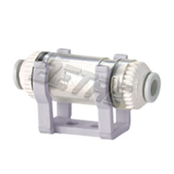
Air Suction Filter(Vacuum Filter) ZFC Series
In-line Type with On-touch Fittings
Characteristic
*An in-line type air suction filter that prevents trouble in vacuum equipment due to contaminants in the air.
*IN/OUT straight piping Saves space with space efficient straight piping
*Applicable tubing sizes: Metric sizes (Release bushing: light gray) ø4, ø6, ø8
*One-touch fittings for easy installation and removal. Piping tube can be connected or disconnected with one touch.
*Light weight molded resin parts.
*Cartridge type allows element replacement.
*The cover can be opened with one touch to allow quick replacement without tools while still connected to piping.
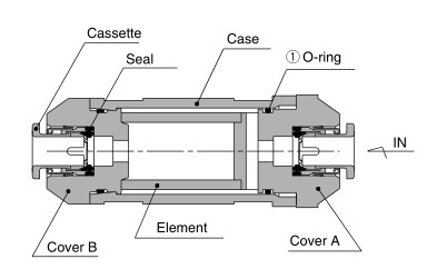
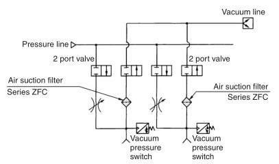
Construction
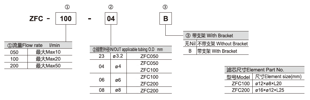
How to Order
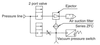
Application
Model
| Model | Port Size (Applicable tubing O.D.) | Recommended Flow Rate (L/min) | Note | |
| IN side, OUT side | ||||
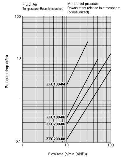
| Metric Size | ZFC100-04 | Ø4 | 10 | Flow Rate when initial pressure drop is 3kPa or less |
| ZFC100-06 | Ø6 | 20 | ||
| ZFC200-06 | Ø6 | 30 | ||
| ZFC200-08 | Ø8 | 50 | ||
Specification
| Fluid | Air, Nitrogen |
| Operating Pressure | -100~0kPa |
| Burst Pressure | 0.5MPa |
| Operating & Ambient Temperature Range | 0 to 60°C (No freezing) |
| Filtration degree | 10 µm |
| Element differential pressure resistance | 0.15 MPa |
| Applicable tubing material | Nylon, Soft nylon, Polyurethane, Soft polyurethane |
| Note | Do not use in a line where a pressurized condition is maintained since the body may be damaged. |
Flow Characteristics
Dimension
.jpg)
| Model | A | B | C | D | E | ØF | ØG | ØH | I | J | K | L |
| ZFC050-23 | 58 | 12.5 | 33 | 12.5 | 25 | 10 | - | 10.5 | 12 | 8.5 | 13.8 | 3.2 |
| ZFC050-04 | 4 | |||||||||||
| ZFC100-04 | 53.2 | 9.1 | 30 | 14.1 | 10 | 18 | 11.6 | 19.5 | 23 | 20 | 29 | 4 |
| ZFC100-06 | 6 | |||||||||||
| ZFC200-06 | 67 | 15.5 | 34 | 17.5 | 14 | 22 | 15.6 | 23.1 | 27 | 24 | 35 | 6 |
| ZFC200-08 | 8 |
Element Replacement
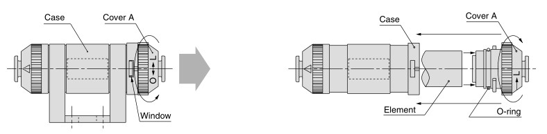
1. Stop operation and reduce the filter's internal pressure to atmosphere.
2. Turn cover A counterclockwise until it stops (approx. 45°).
3. Pull cover A out of the case to remove the element. Remove dust and other debris remaining inside the case by blowing it out with air, etc. (Also confirm that the O-ring is not damaged.)
4. Install a new element on cover A and insert it into the case.
5. After aligning the projections (2 places) on cover A with the grooves in the case, push cover A in and turn it clockwise until it
stops (approx. 45°) (Confirm that the projections on cover A can be seen completely through the windows in the case.)
6. Restart operation.