PRODUCT CATEGORY
CONTACT US
YUEQING BETRE AUTOMATION CO.,LTD. Add:Baishi Industrial, Yueqing, Zhejiang, CN Contact Person: Betre H Tel:+86-577-61712130 Fax:+86-577-61712160 Email:betre@betre.cc MSN:betreauto@hotmail.com SKYPE:betreauto
Skype:
Skype:

CY3B Series Rodless Cylinder
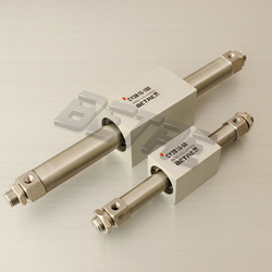
CY3B Series Rodless Cylinder
Rodless Cylinder CY3B Series
Specification
Note) When vertically mounting, it is impossible to perform an intermediate stop by means of a pneumatic circuit.
Strokes
Note 1) Long stroke specification (XB11) applies to the strokes exceeding 2000 mm.
Note 2) The longer the stroke, the larger the amount of deflection in a cylinder tube. Pay attention to the mounting bracket and clearance value.
Note 3) Intermediate stroke is available by the 1 mm interval.
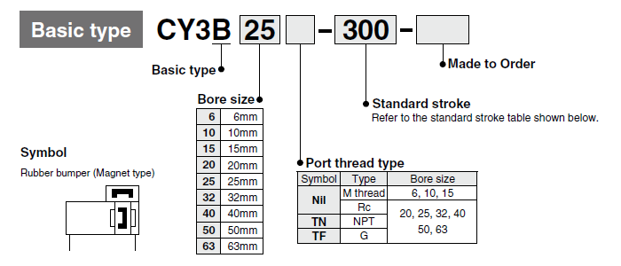
Ordering Information
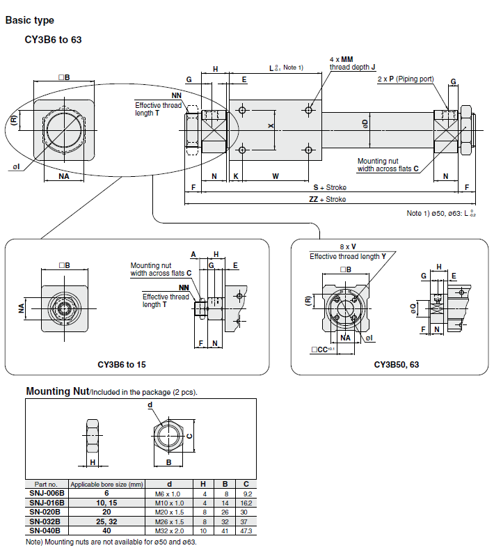
Dimension
Specification
| Bore size(mm) | 6 | 10 | 15 | 20 | 25 | 32 | 40 | 50 | 63 | ||
| Fluld | Air | ||||||||||
| Proof pressure | 1.05MPa | ||||||||||
| Max.operating pressure | 0.7MPa | ||||||||||
| Min.operating pressure | 0.16 | 0.16 | 0.16 | 0.16 | 0.15 | 0.14 | 0.12 | 0.12 | 0.12 | ||
| Amblent and fluld temperature | -10 to 60℃ (No freezing) | ||||||||||
| Piston speed | 50 to 500 mm/s | ||||||||||
| Cushion | Rubber bumper | ||||||||||
| Lubrication | Not required (Non-lube) | ||||||||||
| Stroke length tolerance(mm) | 0 to 250 st: +1.0~0 , 251 to 1000 st: +1.4~0, 1001 st to: +1.8~0 | ||||||||||
| Mounting orientation | Horizontal,Inclined,Vertical Note) | ||||||||||
| Mounting nut(2 pcs.) | Standard equipment (accessory) | ||||||||||
| Magnet holding force(N) | 19.6 | 53.9 | 137 | 231 | 363 | 588 | 922 | 1471 | 2256 | ||
Strokes
|
Bore size (mm) |
Standard stroke (mm) |
Maximum available stroke(mm) |
|||||
| 6 | 50,100,150,200 | 300 | |||||
| 10 | 50,100,150,200,250,300 | 500 | |||||
| 15 | 50,100,150,200,250,300,350,400,450,500 | 1000 | |||||
| 20 | 100,150,200,250,300,350,400,450,500,600, 700, 800 | 1500 | |||||
| 25 | 3000 | ||||||
| 32 | |||||||
| 40 | 100,150,200,250,300,350,400,450,500,600,700, 800,900,1000 | 3000 | |||||
| 50 | 5000 | ||||||
| 63 | |||||||
Note 2) The longer the stroke, the larger the amount of deflection in a cylinder tube. Pay attention to the mounting bracket and clearance value.
Note 3) Intermediate stroke is available by the 1 mm interval.
Ordering Information
Dimension
| Model | A | B | C | CC | D | E | F | G | H | I | J | K | L | MM | N | NA | NN | Q | R | S | T | V | W | X | Y | ZZ | P (Piping port) | |||
| Nil | TN∗ | TF∗ | ||||||||||||||||||||||||||||
| CY3B6 | 4 | 17 | 8∗ | - | 7.6 | 4 | 8∗ | 5 | 13.5∗ | - | 4.5 | 5 | 35 | M3×0.5 | 9.5∗ | 10∗ | M6×1∗ | - | - | 62∗ | 6.5 | - | 25 | 10 | - | 78∗ | M3×0.5∗ | - | - | |
| CY3B10 | 4 | 25 | 14 | - | 12 | 1.5 | 9 | 5 | 12.5 | - | 4.5 | 4 | 38 | M3×0.5 | 11 | 14 | M10×1 | - | - | 63 | 7.5 | - | 30 | 16 | - | 81 | M5×0.8 | - | - | |
| CY3B15 | 4 | 35 | 14 | - | 16.6∗ | 2 | 10 | 5.5 | 13 | - | 6 | 11 | 57 | M4×0.7 | 11 | 17 | M10×1 | - | - | 83 | 8 | - | 35 | 19 | - | 103 | M5×0.8 | - | - | |
| CY3B20 | 8 | 36 | 26 | - | 21.6∗ | 2∗ | 13 | 7.5∗ | 20 | 28 | 6 | 8 | 66 | M4×0.7 | 18∗ | 24 | M20×1.5 | - | 12∗ | 106 | 10 | - | 50 | 25 | - | 132 | Rc1/8 | NPT1/8 | G 1/8 | |
| CY3B25 | 8 | 46 | 32 | - | 26.4∗ | 2∗ | 13 | 7.5∗ | 20.5 | 34 | 8 | 10 | 70 | M5×0.8 | 18.5∗ | 30 | M26×1.5 | - | 15∗ | 111 | 10 | - | 50 | 30 | - | 137 | Rc1/8 | NPT1/8 | G 1/8 | |
| CY3B32 | 8 | 60 | 32 | - | 33.6∗ | 2∗ | 16 | 8∗ | 22 | 40 | 8 | 15 | 80 | M6×1 | 20∗ | 36 | M26×1.5 | - | 18∗ | 124 | 13 | - | 50 | 40 | - | 156 | Rc1/8 | NPT1/8 | G 1/8 | |
| CY3B40 | 10 | 70 | 41 | - | 41.6∗ | 3∗ | 16 | 11 | 29 | 50 | 10 | 16 | 92 | M6×1 | 26∗ | 46 | M32×2 | - | 23∗ | 150 | 13 | - | 60 | 40 | - | 182 | Rc1/4 | NPT1/4 | G 1/4 | |
| CY3B50 | - | 86 | - | 32 | 52.4∗ | 8 | 2 | 14 | 33 | 58∗ | 12 | 25 | 110 | M8×1.25 | 25 | 55 | - | 30 | -0.007 | 27.5∗ | 176 | M8×1.25 | 60 | 60 | 16 | 180 | RC1/4 | NPT1/4 | G 1/4 | |
| -0.037 | ||||||||||||||||||||||||||||||
| CY3B63 | - | 100 | - | 38 | 65.4∗ | 8 | 2 | 14 | 33 | 72∗ | 12 | 26 | 122 | M8×1.25 | 25 | 69 | - | 32 | -0.007 | 34.5∗ | 188 | M10×1.5 | 70 | 70 | 16 | 192 | RC1/4 | NPT1/4 | G 1/4 | |
| -0.043 | ||||||||||||||||||||||||||||||
Note 2) The astrisk denotes the dimensions which are different from the CY1B series.
Note 3) Mounting nuts can be screwed on only for the effective thread length of the head cover (T dimension).
When mounting a cylinder, consider the thickness of flange, etc.

Prev:end Next:CY1S Series Rodless Cylinder