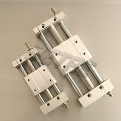
CY1S Series Rodless Cylinder

CY1S Series Rodless Cylinder
Rodless Cylinder CY1S Series
Specification
∗ In the case of setting an auto switch at the intermediate position, the maximum piston speed is subject to restrict for detection upon the response time of a load (relays,sequence controller,etc.).
Strokes

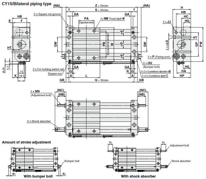
Dimension

Note) The above figures show the product with auto switches. Auto switch and switch spacer are shipped together with the product, but not assembled.
Specification
| Bore size(mm) | 6 | 10 | 15 | 20 | 25 | 32 | 40 | |||
| Fluid | Air | |||||||||
| Proof pressure | 1.05MPa | |||||||||
| Max.operating pressure | 0.7MPa | |||||||||
| Min.operating pressure | 0.18 MPa | |||||||||
| Amblent and fluid temperature | −10 to 60°C (No freezing) | |||||||||
| Piston speed* | 50 to 400 mm/s | |||||||||
| Cushion | Rubber bumper/Shock absorber | |||||||||
| Lubrication | Non-lube | |||||||||
| Stroke length tolerance(mm) | 0 to 250 st:+1.0/0 , 251 to 1000 st:+1.4/0 , 1001st or longer:+1.8/0 | |||||||||
| Magnetic holding force(N) | 19.6 | 53.9 | 137 | 231 | 363 | 588 | 922 | |||
Strokes
| Bore size(mm) | Standard stroke(mm) | Maximum manufacturable stroke (mm) | |||||||
| 6 | 50,100,150,200 | 300 | |||||||
| 10 | 50,100,150,200,250,300 | 500 | |||||||
| 15 | 50,100,150,200,250,300,350,400,450,500 | 750 | |||||||
| 20 | 100,150,200,250,300,350,400,450,500,600,700, 800 | 1000 | |||||||
| 25 | 1500 | ||||||||
| 32 | |||||||||
| 40 | 100,150,200,250,300,350,400,450,500,600,700, 800,900,1000 | 1500 | |||||||
Note 1) Intermediate stroke is available by the 1 mm interval. (Produced upon receipt of order)
Note 2) Minimum stroke available without auto switch or with one auto switch is 15 mm and minimum 25 mm for with 2 auto switches.
Note 3) For 2 or more auto switches with stroke less than 25 mm (minimum 15 mm), consider “-X431” (2 switch rails).
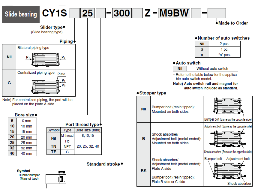
Ordering Information
Dimension

| Model | A | B | C | D | d | E | F | G | GA | GB | GP | H | HA | HB | HC | HG | HP | HT | JJ | K | L | LD | M | MM | NA |
| CY1S6-Z | 6 | 6.5 | 3.3 | 7.6 | 8 | 2 | 25 | 5 | 5 | 5 | 30 | 27 | 20.5 | 20.5 | 15.5 | 8 | 26 | 15.5 | M4x0.7 | 3 | 40 | 3.5 | 6 | M4x0.7 | 11 |
| CY1S10-Z | 7.5 | 8 | 4.4 | 12 | 10 | 2.5 | 31.5 | 6.5 | 5 | 6 | 40 | 34 | 25 | 27 | 17 | 13.5 | 33 | 17 | M4x0.7 | 6 | 45 | 4.6 | 6 | M4x0.7 | 10.5 |
| CY1S15-Z | 7.5 | 9.5 | 5.4 | 16.6 | 12 | 2 | 38 | 6.5 | 5 | 6 | 52 | 40 | 28 | 29.5 | 20.5 | 15 | 39 | 20.5 | M4x0.7 | 11 | 60 | 5.8 | 8 | M5x0.8 | 10.5 |
| CY1S20-Z | 10 | 9.5 | 5.4 | 21.6 | 16 | 2 | 44 | 8.5 | 5.5 | 8 | 62 | 46 | 36 | 37.5 | 24 | 19 | 45 | 20 | M6x1 | 16 | 70 | 5.8 | 10 | M6x1 | 10.5 |
| CY1S25-Z | 10 | 11 | 6.5 | 26.4 | 16 | 2 | 52 | 8.5 | 5.5 | 8 | 70 | 54 | 40.5 | 40.5 | 27.5 | 21.5 | 53 | 21 | M6x1 | 20 | 70 | 7 | 10 | M6x1 | 12.5 |
| CY1S32-Z | 12.5 | 14 | 8.6 | 33.6 | 20 | 2 | 64 | 9.5 | 5.5 | 9 | 86 | 66 | 50 | 50 | 33 | 26 | 64 | 24 | M8x1.25 | 26 | 85 | 9 | 12 | M8x1.25 | 11.5 |
| CY1S40-Z | 12.5 | 14 | 8.6 | 41.6 | 25 | 2 | 74 | 10.5 | 5.5 | 10 | 104 | 76 | 55.5 | 55.5 | 38 | 27 | 74 | 27 | M8x1.25 | 28 | 95 | 9 | 12 | M8x1.25 | 10.5 |
| Model | NB | NC | NN | P | PA | PB | PW | Q | QW | R | R1 | Bumper bolt adjustable range (Both sides: R1x2) | S | T | UU | W | Y1 |
Adjustment bolt adjustable range (Both sides: Y1x2) |
Z |
Shock absorber |
||||
| Nil | TN | TF | ||||||||||||||||||||||
| CY1S6-Z | 14 | 19 | M4x0.7 | M3x0.5 | - | - | 25 | 25 | 49 | 52 | 16 | 1 | 7.5 | 15 | 42 | 10 | M6x0.75 | 46 | 11.5 | 23 | 62 | RJ0604N | ||
| CY1S10-Z | 16.5 | 28 | M4x0.7 | M5x0.8 | - | - | 25 | 38 | 61 | 60 | 24 | 1 | 5.5 | 11 | 47 | 12.5 | M8x1 | 58 | 14 | 28 | 72 | RJ0806HN | ||
| CY1S15-Z | 16.5 | 28 | M4x0.7 | M5x0.8 | - | - | 30 | 50 | 76 | 75 | 30 | 1 | 4.5 | 11 | 62 | 12.5 | M8x1 | 73 | 14 | 28 | 87 | RJ0806LN | ||
| CY1S20-Z | 22 | 28 | M6x1 | Rc1/8 | NPT1/8 | G1/8 | 40 | 70 | 90 | 90 | 38 | 1.5 | 4.5 | 9 | 73 | 16.5 | M10x1 | 87 | 18.5 | 37 | 106 | RJ1007LN | ||
| CY1S25-Z | 22 | 49 | M6x1 | Rc1/8 | NPT1/8 | G1/8 | 40 | 70 | 99 | 90 | 42 | 1.5 | 4.5 | 9 | 73 | 16.5 | M14x1.5 | 96 | 18.5 | 37 | 106 | RJ1412LN | ||
| CY1S32-Z | 23.5 | 52 | M8x1.25 | Rc1/8 | NPT1/8 | G1/8 | 40 | 75 | 119 | 110 | 50 | 3 | 5.5 | 11 | 91 | 18.5 | M20x1.5 | 116 | 18.5 | 37 | 128 | RJ2015HN | ||
| CY1S40-Z | 22.5 | 51 | M8x1.25 | Rc1/4 | NPT1/4 | G1/4 | 65 | 105 | 142 | 120 | 64 | 2 | 4.5 | 9 | 99 | 20.5 | M20x1.5 | 139 | 17.5 | 35 | 140 | RJ2015LN | ||


