Mini Cylinder CJ2 Series
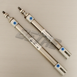
Mini Cylinder CJ2 Series
Mini Cylinder Series CJ2
.png)
Specifications
Standard Strokes (mm)
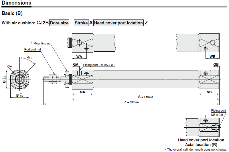
Unit: mm
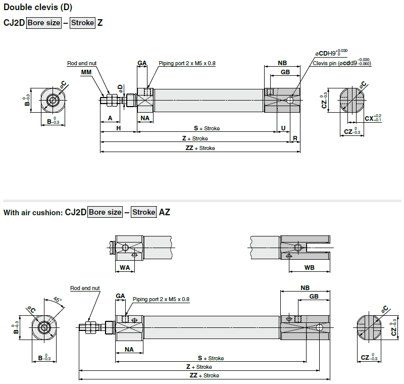
* A clevis pin and retaining rings are included. Unit: mm
With Air Cushion/Dimensions other than the table below are the same as the table above. Unit: mm
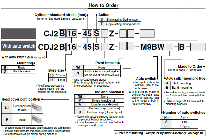
Specifications
Standard Strokes Unit: mm
.png)
Specifications
| Bore size (mm) | 6 | 10 | 16 | ||||||
| Action | Double acting, Single rod | ||||||||
| Fluid | Air | ||||||||
| Proof pressure | 1 MPa | ||||||||
| Maximum operating pressure | 10.7 MPa | ||||||||
| Minimum operating pressure | Rubber bumper | 0.12 MPa | 0.06 MPa | ||||||
| Air cushion | - | 0.1 MPa | |||||||
| Ambient and fluid temperature | Without auto switch: –10°C to 70°C (No freezing) With auto switch: –10°C to 60°C | ||||||||
| Cushion | Rubber bumper | Rubber bumper/Air cushion | |||||||
| Lubrication | Not required (Non-lube) | ||||||||
| Piston speed | Rubber bumper | 50 to 750 mm/s | |||||||
| Air cushion | - | 50 to 1000 mm/s | |||||||
| Allowable kinetic energy | Rubber bumper | 0.012 J | 0.035 J | 0.090 J | |||||
|
Air cushion (Effective cushion length) |
- |
0.07 J (9.4 mm) |
0.18 J (9.4 mm) |
||||||
| Stroke length tolerance | +1.0mm~0 mm | ||||||||
Standard Strokes (mm)
| Bore size | Standard stroke | Maximum manufacturable stroke |
| 6 | 15, 30, 45, 60 | 200 |
| 10 | 15, 30, 45, 60, 75, 100, 125, 150 | 400 |
| 16 | 15, 30, 45, 60, 75, 100, 125, 150, 175, 200 | 400 |
* Manufacture of intermediate strokes at 1 mm intervals is possible. (Spacers are not used.)Produced upon receipt of order.
* Applicable strokes should be confirmed according to the usage. For details, refer to “Air Cylinders Model Selection” on front matter pages of the Best Pneumatics No. 2 or the WEB catalog. In addition, the products that exceed the standard stroke might not be able to fulfill the specifications due to the deflection etc.
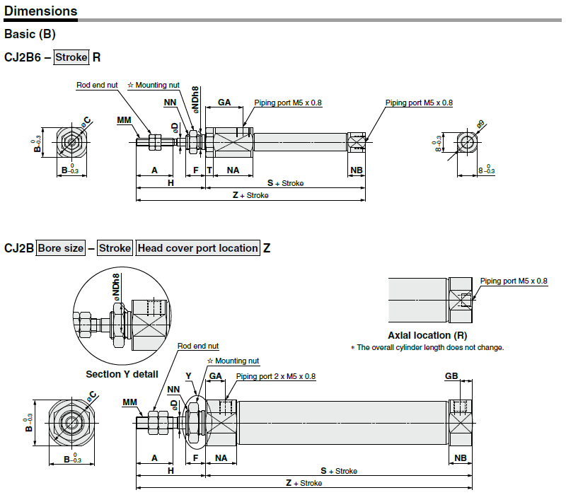
Unit:mm

Unit:mm
| Bore size | A | B | C | D | F | GA | GB | H | MM | NA | NB | NDh8 | NN | S | T | Z | |
| 6 | 15 | 12 | 14 | 3 | 8 | 14.5 | - | 28 | M3x0.5 | 16 | 7 | 6 | 0 | M6x1.0 | 49 | 3 | 77 |
| -0.018 | |||||||||||||||||
| 10 | 15 | 12 | 14 | 4 | 8 | 8 | 5 | 28 | M4x0.7 | 12.5 | 9.5 | 8 | 0 | M8x1.0 | 46 | - | 74 |
| -0.022 | |||||||||||||||||
| 16 | 15 | 18.3 | 20 | 5 | 8 | 8 | 5 | 28 | M5x0.8 | 12.5 | 9.5 | 10 | 0 | M10x1.0 | 47 | - | 75 |
| -0.022 | |||||||||||||||||

Unit: mm
| Bore size | B | C | GA | GB | NA | NB | WA | WB | S | Z |
| 10 | 15 | 17 | 7.5 | 6.5 | 21 | 20 | 14.4 | 13.4 | 65 | 93 |
| 16 | 18.3 | 20 | 7.5 | 6.5 | 21 | 20 | 14.4 | 13.4 | 66 | 94 |

* A clevis pin and retaining rings are included. Unit: mm
| Bore Size | A | B | C | CD(cd) | CX | CZ | D | GA | GB | H | MM | NA | NB | R | S | U | Z | ZZ |
| 10 | 15 | 12 | 14 | 3.3 | 3.2 | 12 | 4 | 8 | 18 | 28 | M4 x 0.7 | 12.5 | 22.5 | 5 | 46 | 8 | 82 | 87 |
| 16 | 15 | 18.3 | 20 | 5 | 6.5 | 18.3 | 5 | 8 | 23 | 28 | M5 x 0.8 | 12.5 | 27.5 | 8 | 47 | 10 | 85 | 93 |
| Bore Size | B | C | CZ | GA | GB | NA | NB | WA | WB | S | Z | ZZ |
| 10 | 15 | 17 | 15 | 7.5 | 19.5 | 21 | 33 | 14.4 | 26.4 | 65 | 101 | 106 |
| 16 | 18.3 | 20 | 18.3 | 7.5 | 24.5 | 21 | 38 | 14.4 | 31.4 | 66 | 104 | 112 |

Specifications
| Bore size(mm) | 6 | 10 | 14 | ||||||
| Action | Single acting, Spring return/Single acting, Spring extend | ||||||||
| Fluid | Air | ||||||||
| Proof pressure | 1 MPa | ||||||||
| Max. operating pressure | 10.7 MPa | ||||||||
| Max. operating pressure | Spring return | 0.12 MPa | 0.06 Mpa | ||||||
| Spring extend | - | 0.1 MPa | |||||||
| Ambient and fluid temperature |
Without auto switch: –10°C to 70°C (No freezing) With auto switch: –10°C to 60°C |
||||||||
| Cushion | |||||||||
| Lubrication | Rubber bumper | Rubber bumper/Air cushion | |||||||
| Stroke length tolerance | Not required (Non-lube) | ||||||||
| Piston speed | 50 to 750 mm/s | ||||||||
| Allowable kinetic energy | '+1.0mm~0mm | ||||||||
| Bore size | Standard stroke | ||
| 6 | 15,30,45,60 | ||
| 10 | 15,30,45,60 | ||
| 15 | 15,30,45,60,75,100,125,150 | ||
* Manufacture of intermediate strokes at 1 mm intervals is possible. (Spacers are not used.)
* Please consult with SMC for strokes which exceed the standard stroke length.
* Applicable strokes should be confirmed according to the usage. For details, refer to “Air Cylinders Model Selection” on front matter pages of the Best Pneumatics No. 2 or the WEB catalog. In addition, the products that exceed the standard stroke might not be able to fulfill the specifications due to the deflection etc.
Dimensions
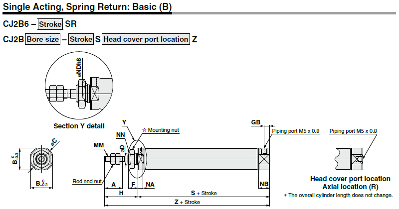
Unit:mm
Dimensions

Unit:mm
| Bore size | A | B | C | D | F | GB | H | MM | NA | NB | NDh8 | NN | S | ||||||||
| 5 to 15 st | 16 to 30 st | 31 to 45 st | 46 to 60 st | 61 to 75 st | 76 to 100 st | 101 to 125 st | 126 to 150 st | ||||||||||||||
| 6 | 15 | 8 | 9 | 3 | 8 | - | 28 | M3x0.5 | 3 | 7 | 6 | 0 | M6x1.0 | 34.5 (39.5) | 43.5 (48.5) | 47.5 (52.5) | 61.5 (66.5) | - | - | - | - |
| -0.018 | |||||||||||||||||||||
| 10 | 15 | 12 | 14 | 4 | 8 | 5 | 28 | M4x0.7 | 4.8 | 9.5 | 8 | 0 | M8x1.0 | 45.5 | 53 | 65 | 77 | - | - | - | - |
| -0.022 | |||||||||||||||||||||
| 16 | 15 | 18.3 | 20 | 5 | 8 | 5 | 28 | M5x0.8 | 4.8 | 9.5 | 10 | 0 | M10x1.0 | 45.5 | 54 | 66 | 78 | 84 | 108 | 126 | 138 |
| -0.022 | |||||||||||||||||||||
| Bore size | Z | |||||||
| 5 to 15 st | 16 to 30 st | 31 to 45 st | 46 to 60 st | 61 to 75 st | 76 to 100 st | 101 to 125 st | 126 to 150 st | |
| 6 | 62.5(67.5) | 71.5(76.5) | 75.5(80.5) | 89.5(94.5) | - | - | - | - |
| 10 | 73.5 | 81 | 93 | 105 | - | - | - | - |
| 16 | 73.5 | 82 | 94 | 106 | 112 | 136 | 154 | 166 |


